Frigidaire FGMC3065PF Installation Manual
Browse online or download Installation Manual for Microwaves Frigidaire FGMC3065PF. Frigidaire FGMC3065PF Installation Instructions User Manual
- Page / 18
- Table of contents
- BOOKMARKS
- INSTALLATION INSTRUCTIONS 1
- IMPORTANT SAFETY 2
- INSTRUCTIONS 2
- INSTRUCCIONES 8
- IMPORTANTES DE SEGURIDAD 8
- INSTRUCCIONES DE INSTALACIÓN 10
- Moldura 11
- Tornillos 11
- Pièce nº 807611001 (1304) 13
- Rév. A English – pages 1-6 13
- États-Unis 13
- MESURES DE SÉCURITÉ 14
- IMPORTANTES 14
- 3. Connexion électrique 15
- REMARQUE IMPORTANTE 16
- Risque de basculement 17
Summary of Contents
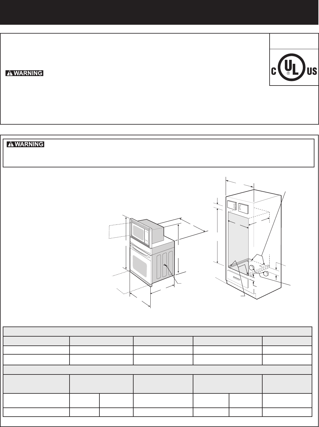
1MICROWAVE/ WALL OVEN COMBINATIONINSTALLATION INSTRUCTIONSBADFIHG11½”(29.2 cm)11½”(29.2 cm)1¼”(3.2 cm)Min.1¼”(3.2 cm)Min.3” (7.6 cm)Max.3” (7.6 cm)Max
4COMBINACIÓN DE HORNO DE PARED/HORNO MICROONDAS INSTRUCCIONES DE INSTALACIÓNUbicación de la placa de número de modelo y de serieLa placa de serie se u
5COMBINACIÓN DE HORNO DE PARED/HORNO MICROONDAS INSTRUCCIONES DE INSTALACIÓNFigura 6Figura 7Moldura inferiorTornillos proporcionados6. Instale los to
6COMBINACIÓN DE HORNO DE PARED/HORNO MICROONDAS INSTRUCCIONES DE INSTALACIÓN7. Vericación del funcionamientoSu modelo viene equipado con un control d
1INSTRUCTIONS D'INSTALLATION DE LA COMBINAISON DE FOURS À MICRO-ONDES ET ENCASTRÉBADFIHG29,2 cm (11½ po)3,2 cm (1¼ po)min.7,6 cm (3 po) max.2,5
2INSTRUCTIONS D'INSTALLATION DE LA COMBINAISON DE FOURS À MICRO-ONDES ET ENCASTRÉRemarques importantes pour l'installateur1. Lisez toutes
3INSTRUCTIONS D'INSTALLATION DE LA COMBINAISON DE FOURS À MICRO-ONDES ET ENCASTRÉFigure 3BOÎTE DE JONCTION MISE À LA TERRE À 3 FILSCâble de l’al
4INSTRUCTIONS D'INSTALLATION DE LA COMBINAISON DE FOURS À MICRO-ONDES ET ENCASTRÉEmplacement du numéro de modèle et du numéro de sérieLa plaque
5INSTRUCTIONS D'INSTALLATION DE LA COMBINAISON DE FOURS À MICRO-ONDES ET ENCASTRÉFigure 6Figure 7Garniture inférieureVis fournies6. Installez l
6INSTRUCTIONS D'INSTALLATION DE LA COMBINAISON DE FOURS À MICRO-ONDES ET ENCASTRÉ7. Vérication de l'opérationVotre modèle est muni d'
2MICROWAVE/ WALL OVEN COMBINATIONINSTALLATION INSTRUCTIONSImportant Notes to the Installer1. Read all instructions contained in these installation in
3MICROWAVE/ WALL OVEN COMBINATIONINSTALLATION INSTRUCTIONSFigure 33-WIRE GROUNDED JUNCTION BOXCable from Power SupplyBlack WiresJunction BoxCable from
4MICROWAVE/ WALL OVEN COMBINATIONINSTALLATION INSTRUCTIONSModel and Serial Number LocationThe serial plate is located along the interior side trim of
5MICROWAVE/ WALL OVEN COMBINATIONINSTALLATION INSTRUCTIONSFigure 6Figure 7Bottom TrimScrews supplied6. Install the Anti-tip Mounting Screws The wall
6MICROWAVE/ WALL OVEN COMBINATIONINSTALLATION INSTRUCTIONS7. Checking OperationYour model is equipped with an Electronic Oven Control. Each of the fun
1COMBINACIÓN DE HORNO DE PARED/HORNO MICROONDAS INSTRUCCIONES DE INSTALACIÓN,LA INSTALACIÓN Y EL SERVICIO DEBEN SER REALIZADOS POR UN INSTALADOR CALIF
2COMBINACIÓN DE HORNO DE PARED/HORNO MICROONDAS INSTRUCCIONES DE INSTALACIÓNNotas importantes para el instalador1. Antes de instalar la combinación d
3COMBINACIÓN DE HORNO DE PARED/HORNO MICROONDAS INSTRUCCIONES DE INSTALACIÓNFigura 3CAJA DE EMPALME DE CONEXIÓN A TIERRA DE 3 CABLESCable del suminist
More documents for Microwaves Frigidaire FGMC3065PF


Related products and manuals for Microwaves Frigidaire FGMC3065PF
 (24 pages)
(21 pages)
(16 pages)
(24 pages)
(21 pages)
(16 pages)
 (12 pages)
(26 pages)
(24 pages)
(12 pages)
(26 pages)
(24 pages)
 (24 pages)
(21 pages)
(26 pages)
(24 pages)
(29 pages)
(20 pages)
(25 pages)
(29 pages)
(12 pages)
(24 pages)
(24 pages)
(21 pages)
(26 pages)
(24 pages)
(29 pages)
(20 pages)
(25 pages)
(29 pages)
(12 pages)
© 2020, manymanuals.com. All rights reserved. | 1.856 s |
 Manymanuals.com
 Manymanuals.de
 Manymanuals.fr
 Manymanuals.it
 Manymanuals.pl
 Manymanuals.cz
 Manymanuals.es
 Manymanuals-pt.com
Comments to this Manuals